PhotoRobot SynchroBox - Funzjonalità u Gwida għall-Utent ta' Setup
Id-dokumentazzjoni li ġejja tiddeskrivi l-funzjonalità u s-setup ta' PhotoRobot SynchroBox, il-Kontrollur Multi-Kamera li jappoġġja l-PhotoRobot MultiCam. Din l-informazzjoni għandha l-għan li tappoġġja lill-klijenti ta' PhotoRobot li reċentement xtraw apparat u qed jużaw aktar minn kamera waħda ma' PhotoRobot. Is-SynchroBox tiffunzjona bħala hub multi-kamera li tissinkronizza l-shutter tal-kamera ta' żewġ kameras jew aktar. Kompli aqra biex tifhem it-teorija, il-funzjonalità, u s-setup tas-SynchroBox biex tgħin tiffaċilita l-fehim bażiku u l-ewwel operazzjoni tal-apparat.
Importanti: L-installazzjoni inizjali ta' sistema PhotoRobot għandha dejjem titwettaq minn awtorità PhotoRobot awtorizzata. Awtoritajiet b'awtorizzazzjoni biex jinstallaw PhotoRobot huma distributur approvat, jew rappreżentant tal-manifattur innifsu. Barra minn hekk, dejjem irreferi għal Informazzjoni dwar is-Sigurtà u Istruzzjonijiet ta' PhotoRobot flimkien ma' kwalunkwe manwal ipprovdut speċifikament mal-apparat tiegħek qabel l-ewwel użu ta' PhotoRobot.
Nota: Għal istruzzjonijiet dwar l-assemblaġġ u l-ewwel użu tal-PhotoRobot MULTICAM, irreferi għal Installazzjoni tal-PhotoRobot MULTICAM u CENTERLESS TABLE.
Gwida Teknika għall-Utent ta' SynchroBox
Grazzi u prosit għax-xiri tiegħek ta' PhotoRobot. PhotoRobot tirrappreżenta għexieren ta' snin ta' esperjenza professjonali diretta u innovazzjoni fil-fotografija awtomatizzata. Kull apparat jipprovdi ekosistema ta' soluzzjonijiet lesti, b'karatteristiċi adattati għall-bżonnijiet uniċi tan-negozju tiegħek.
Merħba f'PhotoRobot. Uża l-informazzjoni teknika li ġejja biex tibda l-vjaġġ tiegħek biex tifhem u tmassimizza l-produzzjoni fl-istudjo mmexxi minn PhotoRobot.
1. PhotoRobot SynchroBox - It-Teorija
Il-PhotoRobot SynchroBox huwa meħtieġ biex jissinkronizza l-shutter tal-kamera meta jintużaw żewġ kameras jew aktar b'sistemi PhotoRobot. SynchroBox jaħdem bħala hub b'ħafna kameras biex jissinkronizza l-qbid ta' frejms individwali minn kameras differenti fil-mument preċiż. Jirrappreżenta soluzzjoni għall-problema li toħroġ meta taħdem ma' kameras li għandhom dewmien differenti tal-shutter, u tappoġġja sa 8 kameras b'mod totali.
Biex tifhem it-teorija tas-SynchroBox, ħu pereżempju s-sekwenzi tal-modalità standard ta' cattura kontra l-modalità ta' cattura fast-spin ma' PhotoRobot.
Fil-modalità standard ta' cattura, hemm is-sekwenza li ġejja.
a) Il-pjanċa timxi għall-angolu mixtieq.
b) Il-pjanċa tieqaf.
c) Il-kamera tieħu ritratti tal-oġġett.
d) Il-pjanċa tibda timxi għall-angolu li jmiss.
M'hemm l-ebda aġġustament meħtieġ f'dan is-sitwazzjoni.
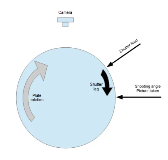
Fil-modalità ta' qbid rapidu, is-sekwenza teħtieġ diversi stadji oħra.
a) Il-pjanċa tibda ddur b'veloċità predefinita.
b) L-Unità ta' Kontroll tirrikonoxxi l-angolu ta' qbid li qed jersaq.
c) L-Unità ta' Kontroll tispara l-shutter tal-kamera permezz ta' kejbil tal-shutter minn qabel.
d) Il-kamera tibda l-proċess ta' qbid (moviment tal-kurtiera tas-sensur, eċċ).
e) Il-proċess tal-qbid jeħtieġ madwar 50 millisekonda ("shutter lag").
f) Il-pjanċa tkun kontinwament qed tiċċaqlaq matul il-perjodu ta' dewmien tal-shutter.
g) Il-pjanċa tilħaq l-angolu mixtieqa eżattament meta l-lag tal-shutter tal-kamera jispiċċa, jieħu r-ritratt.
h) L-Unità ta' Kontroll tirrikonoxxi li l-angolu tal-qbid li jmiss qed jersaq, u tirrepeti l-proċess tal-qbid fir-rigward tal-lag tal-shutter.
i) Ir-rotazzjoni tal-pjanċa tispiċċa wara 360 grad, u twaqqaf kull moviment.
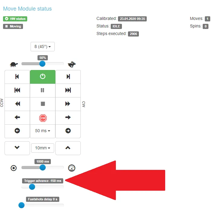
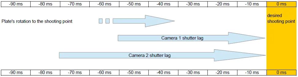
Nota: Minħabba li kull kamera għandha dewmien differenti tal-shutter, huwa meħtieġ li jiġu aġġustati l-avvanz tal-ottur tal-Unità ta' Kontroll għal kull kamera partikolari. Dan huwa possibbli għall-Unità ta' Kontroll (Ġenerazzjoni 6) permezz tal-interface grafika tas-servizz tagħha billi tuża l-għażla "Trigger advance". Il-valur ta' "Trigger advance" irid ikun ogħla mill-lag tal-shutter tal-kamera. Per eżempju, jekk id-dewmien tal-shutter tal-kamera huwa ta' 80 ms, allura l-"Trigger advance" għandu jkun kważi ugwali jew akbar minn 90 ms.
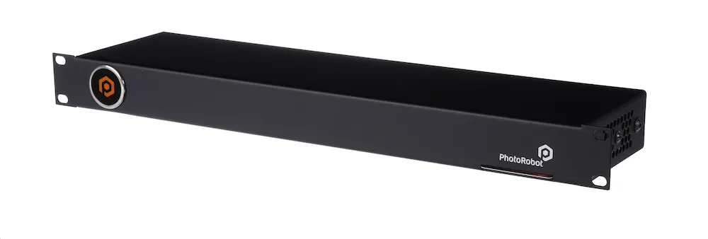
2. Deskrizzjoni tal-Apparat - PhotoRobot SynchroBox
B'disinn, is-SynchroBox huwa apparat rack mount iddisinjat għas-sinkronizzazzjoni tal-shutters tal-kamera ta' żewġ kameras jew aktar. Huwa meħtieġ meta wieħed joperaw kwalunkwe sistema PhotoRobot billi tuża aktar minn kamera waħda fl-istess ħin. One SynchroBox jappoġġja sa 8 kameras, u jipprovdi soluzzjoni biex taħdem madwar diversi dewmien tal-shutter tal-kameras li jkunu qed jintużaw.

Ħu pereżempju xenarju li juża żewġ kameras u SynchroBox biss bħala splitter għal iż-żewġ kameras, mingħajr setup addizzjonali applikat. Fl-istess ħin, il-valur ta' "Trigger advance" tal-Unità ta' Kontroll G6 huwa żero. Il-shutter imbagħad jiġi sparat meta l-pjanċa tilħaq l-angolu mixtieq.
F'dan il-każ, il-passi tas-sekwenza huma:
a) Il-pjanċa tilħaq l-angolu mixtieq.
b) L-Unità ta' Kontroll tispara l-shutter tal-kamera permezz ta' kejbil tal-shutter.
c) Id-dewmien tal-shutter għal iż-żewġ kameras jgħaddi 'l isfel waqt li l-pjanċa tkun f'moviment kontinwu.
d) L-ewwel kamera tieħu r-ritratt 50 ms wara l-punt mixtieqa tal-qbid billi tuża gradi ta' "angolu mixtieqa + X".
e) It-tieni kamera taqbad ir-ritratt 70 ms wara l-punt mixtieqa billi tuża gradi ta' "angolu mixtieqa + Y".
f) Il-gradi tal-valur "Y" huma akbar mill-gradi tal-valur "X".
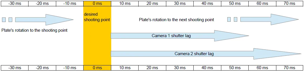
Bħala riżultat, ma jinqabadx ritratt tal-angolu mixtieq. Għalhekk, hemm bżonn ta' aġġustament sabiex iż-żewġ kameras jieħdu ritratti tal-punt ta' qbid mixtieqa fil-mument it-tajjeb.
Għal dan, is-SynchroBox jirċievi puls ta' "shutter fired" mill-Unità ta' Kontroll G6, u awtomatikament jidentifika t-tul tal-puls.
Barra minn hekk, is-SynchroBox għandu l-valur tad-dewmien tal-shutter għal kull kamera konnessa, li ġie daħal manwalment meta ġie ssettjat.
Bl-użu ta' dawn iż-żewġ parametri, is-SynchroBox jgħodd u jattiva l-shutter ta' kull kamera bl-avvanz xieraq.
3. Kif Tkejjel il-Lag tal-Shutter tal-Kamera
Biex tiġi mkejla d-dewmien tal-shutter tal-kamera, huwa meħtieġ li jkollok PhotoRobot b'kwalunkwe pjanċa rotanti, l-Unità ta' Kontroll G6+, u kamera konnessa permezz ta' kejbil tal-shutter mal-Unità ta' Kontroll.
Wara, kompjuter lokali b'PhotoRobot Controls App Software irid ikun konness mal-kamera permezz ta' kejbil USB.
Fl-aħħar, huwa meħtieġ protrattur ta' 360 grad (li jista' jitniżżel online) biex jitlesta l-passi li ġejjin.
a) Poġġi l-protrattur fuq il-pjanċa tal-apparat PhotoRobot, billi tuża kwalunkwe pointer pożizzjonat barra mill-pjanċa u li jindika lejn il-bord.
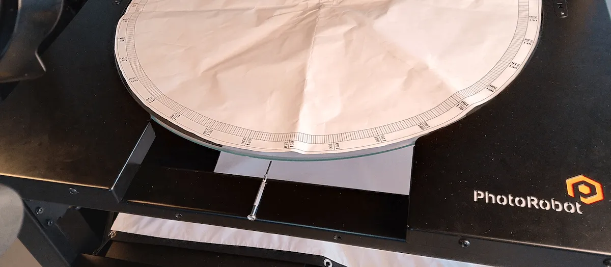
b) Iddur il-pjanċa sakemm il-pointer ikun f'zero. Nota: Dan il-pass huwa possibbli bl-idejn anke meta l-magni elettriċi jkunu mitfija.
c) Ibda s-softwer tal-PhotoRobot Controls App, tidħol fil-kont tiegħek, u toħloq oġġett bl-użu tax-xogħol tal-post tax-xogħol f'moħħok il-konfigurazzjoni mogħtija. Imbagħad, iftaħ il-modalità Captur, u iftaħ il-folder "Other".
d) Imbagħad, f'tab ġdid fuq il-browser tiegħek, iftaħ il-GUI tas-servizz tal-Unità ta' Kontroll (G6), li tipprovdi kontroll fuq il-pjanċa bl-indirizz IP tagħha.
e) Fil-GUI tas-servizz, issettja r-robot b'parametri li ġejjin:
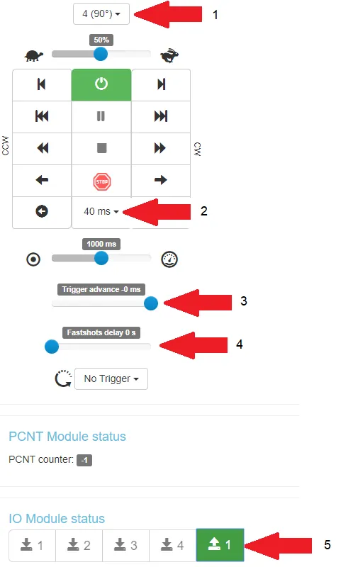
- 1 = 4 ritratti b'90 grad;
- 2 = 40 ms tul ta' impuls biex jitneħħa l-isktar;
- 3 = avvanz tat-trigger 0 ms (l-ebda avvanz);
- 4 = l-ebda dewmien ta' fastshots
- 5 = nofs pressjoni tal-shutter tiġi attivata
f) Ibda s-sekwenza billi tikklikkja l-vleġġa tal-lemin fil-kantuniera t'isfel tal-lemin tal-pannell tal-kontroll:
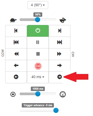
Nota: Is-sekwenza tibda f'90 grad u tispiċċa f'0 grad. Fl-istess ħin, ir-ritratti kollha jinqabdu fil-folder "Other" fl-App tal-Kontrolli, kif kien diġà kkonfigurat.
Per eżempju, irreferi għall-output tal-kampjuni li ġejjin (b'direzzjoni li ddur lejn ix-xellug):
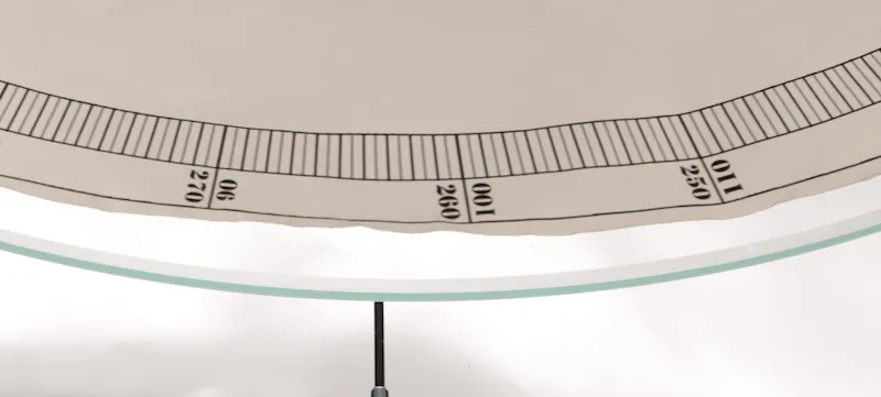
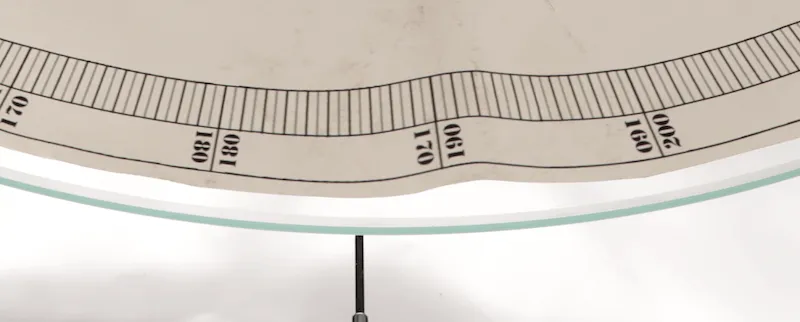
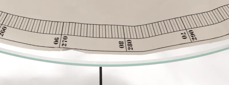
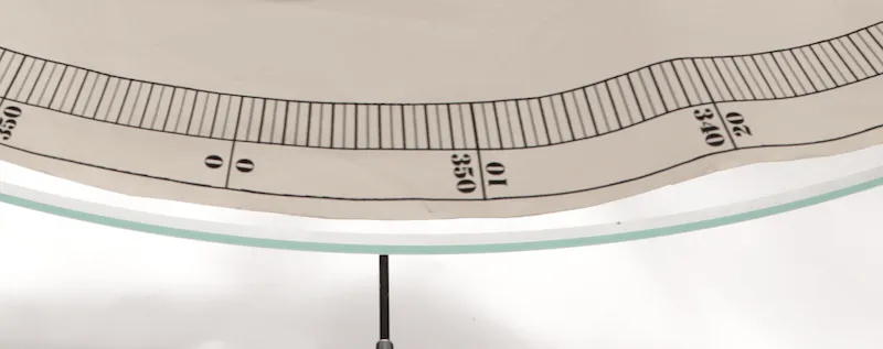
- Nota: F'dawn l-eżempji, il-qbid tal-immaġni kien madwar 6 gradi wara li t-trigger kien sparat.
g) Sussegwentement, biex tinbidel 6 gradi f'numru ta' millisekondi (ms) f'dan il-każ, tibda r-rotazzjoni kontinwa tal-pjanċa ta' PhotoRobot bl-istess veloċità mill-pass preċedenti fil-GUI tas-servizz.
- Ibda stopwatch u rreġistra l-ħin għal 10 rounds.
- F'dan il-każ tat-test, il-valur riżultanti huwa 61 sekonda (61,000 ms).
- Dan ifisser li 10 rounds huma ugwali għal 10 * 360 grad (3,600 grad).
- Hemm moviment ta' żmien ta' 1 grad li jdum 61,000 ms / 3,600 grad, li jammonta għal 16.94 ms.
- Hemm 6 gradi ta' moviment taż-żmien li jdum 16.94 ms * 6, li jammonta għal 101.64 ms.
- Għalhekk, id-dewmien approssimattiv tal-iskturar huwa madwar 102 ms.
h) Fl-aħħar, huwa meħtieġ li jerġgħu jsiru l-passi kollha ta' qabel biex jiġu identifikati d-dewmien tal-iskturar għal kull kamera differenti li qed jintuża.
4. Setup ta' SynchroBox
Għall-setup tas-SynchroBox, rekwiżit huwa li jkun hemm Unit ta' Kontroll (G6) installata u kompletament operattiva. Barra minn hekk, idealment ikun hemm 2 jew aktar kameras mill-istess manifattur u tal-istess mudell, kull waħda b'dewmien ta' shutter magħruf.
F'dan il-każ, uża dawn il-passi biex tissettja s-SynchroBox.
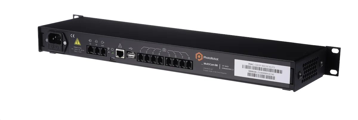
4.1. Ikkonnettja s-SynchroBox mal-Unità ta' Kontroll G6 permezz ta' kejbil tal-shutter. Nota: Dan il-kejbil tal-shutter huwa provdut minn PhotoRobot bħala parti mill-kunsinna ta' SynchroBox, jew taħt in-numru tal-parti KHCAR1R05. Il-kejbil tal-shutter jgħaqqad il-port "OUT" tal-Unità ta' Kontroll G6 mal-port "->IN" tas-SynchroBox (dak iżgħar, mhux l-ieħor "=>IN").
4.2. Ikkonnettja s-SynchroBox man-netwerk permezz ta' kejbil ethernet standard, billi tuża l-istess subnet li jikkonnettja mal-Unità tal-Kontroll.
4.3. Ikkonnettja l-kameras kollha li se jkunu operattivi mas-SynchroBox billi tuża kejbils tal-shutter.
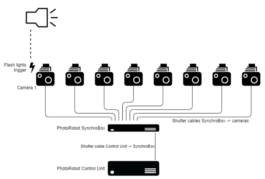
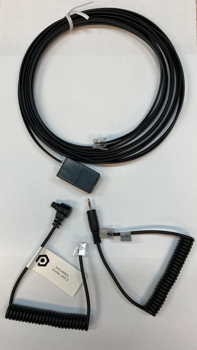
Nota: Il-kejbils tal-shutter għas-SynchroBox għall-kameras jiġu pprovduti minn PhotoRobot taħt in-numri tal-parti KHCARCJ (Canon Jack 2.5 mm Connector) jew KHCARN3 (Canon N3 connector) flimkien mal-estensjoni KHCAR1R05, jew bħala dak li jissejjaħ sett ta' kejbils tal-shutter.
4.4. Oqgħod attent li Kamera 1 (port 1 tas-SynchroBox) iżżomm u topera l-apparat tat-tħaddim tad-dawl tal-flash. Din il-kamera trid ikollha l-akbar dewmien tal-isktur.
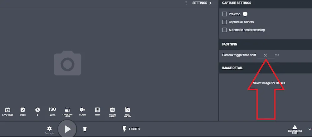
4.5. Issettja l-valur ta' "Trigger advance" tal-Unità ta' Kontroll (G6) skont id-dewmien tal-shutter tal-kamera l-iktar bil-mod (deskritt qabel fis-sezzjoni 1 ta' dan id-dokument). Nota: Meta tuża l-PhotoRobot Controls App, oqgħod attent li dan il-valur jiġi aġġustat / sostitwit bil-valur stabbilit għall-modalità Capture - Fast Spin:
4.6. Imbagħad, aċċessa l-GUI tas-servizz tas-SynchroBox billi daħħal l-indirizz IP tiegħu fil-format URL fil-browser tal-web tiegħek.
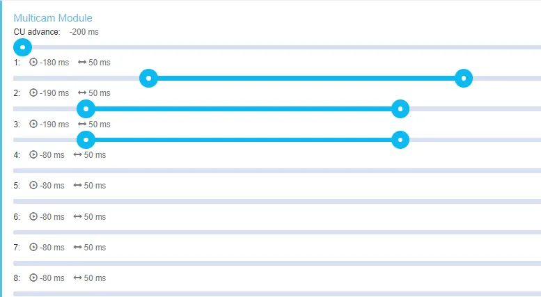
4.7. Issettja l-ewwel slider "CU advance" għall-istess valur bħall-Unità tal-Kontroll, jew għal valur korrispondenti f'PhotoRobot Controls. Nota: Oqgħod attent li jekk dawn iż-żewġ valuri jkunu differenti, il-valur f'PhotoRobot Controls se jkollu prijorità. Imbagħad, hemm 8 sliders li jikkorrispondu għall-8 portijiet fuq is-SynchroBox. Is-sliders għandhom żewġ valuri kull wieħed: l-avvanz (buttuna tax-xellug), u t-tul tal-puls (buttuna tal-lemin). Il-valur avvanzat huwa ugwali għall-lag tal-shutter tal-kamera kkontrollata (bil-valur reali l-iżgħar madwar -50 ms). It-tul tal-puls imbagħad jirrelata mal-perjodu ta' żmien li fih il-kejbil tal-shutter għall-kamera jibqa' f'kuntatt. Dan il-valur jiġi pprovdut mill-manifattur tal-kamera, jew, jekk mhux magħruf, jista' jiġi stabbilit għal 40 - 60 ms.
4.8. Issettja l-kanal tal-input fil-GUI tas-servizz SynchroBox. Nota: Meta jintużaw il-kejbils tal-shutter ta' PhotoRobot, l-issettjar dejjem ikun kif ġej.
- Fil-port: A = fokus, B = trigger
- Port 1 - 8: A = trigger, B = fokus
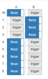
- Innota li hemm biss kameras 1, 2, u 3 imwaqqfa fl-eżempju ta' hawn fuq.
- Peress li PhotoRobot huwa maħsub biex juża dwal tal-flash, issettja l-veloċità tal-iskar tal-kamera 1 għal 1/100 jew 1/125.
4.9. Fl-aħħar, konfigura l-setup inizjali ta' kameras oħra kollha għal veloċità ta' shutter ħafna itwal, eż. 1/30 - 1/60. Dan jgħin biex jiġi kkunsidrat id-differenza possibbli fil-lag tal-shutter bejn il-kameras li qed jintużaw. Il-perjodu ta' żmien itwal jiżgura wkoll li l-kameras kollha jilħqu l-quċċata tal-flash minn kull strob. Meta jaħdem sew, ikun possibbli li wieħed jesperimenta billi jitnaqqas il-veloċità tal-shutter tal-kameras l-oħra jekk ikun meħtieġ.
5. Setup Multiplu ta' SynchroBox
Is-SynchroBox jappoġġja sa massimu ta' 8 kameras. Jekk ikunu meħtieġa aktar minn 8 kameras, huwa possibbli li jiġu multiplikati n-numru ta' SynchroBoxes li qed jintużaw.
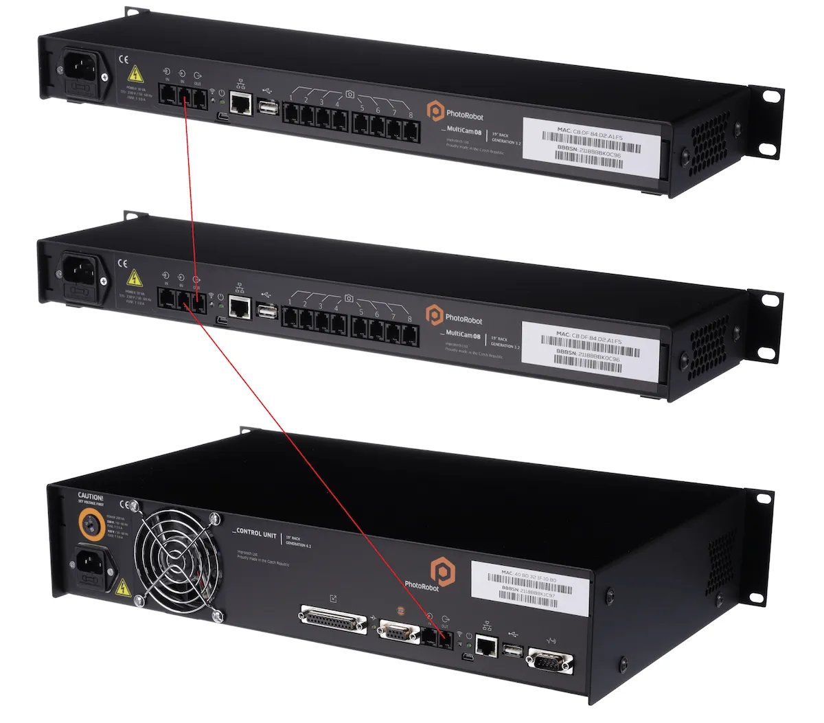
- Ikkonnettja l-port OUT tal-ewwel SynchroBox mal-port IN tas-SynchroBox li jmiss, billi tuża l-istess kejbil tal-shutter li jgħaqqad l-Unità ta' Kontroll mas-SynchroBox. Dan il-kejbil tal-shutter huwa provdut minn PhotoRobot bħala parti mill-kunsinna ta' SynchroBox jew taħt in-numru tal-parti KHCAR1R05.


Serje Ribelli EOS


Serje DSLR EOS


EOS M Serje Bla Mera


Serje PowerShot


Close-Up / Miżmum fl-Idejn

Il-Canon EOS Rebel Series toffri kameras DSLR favur il-bidu bi kwalità ta 'immaġni solida, kontrolli intuwittivi, u karatteristiċi versatili. Ideali għad-dilettanti tal-fotografija, dawn il-kameras jipprovdu autofocus affidabbli, touchscreens ta 'angolu varji, u reġistrazzjoni tal-vidjow Full HD jew 4K.
Konnessjoni
Riżoluzzjoni (MP)
Riżoluzzjoni
Is-Serje Canon EOS DSLR tagħti immaġini ta 'kwalità għolja, autofocus veloċi, u versatilità, li tagħmilha ideali kemm għall-produzzjoni tal-fotografija kif ukoll tal-vidjow.
Konnessjoni
Riżoluzzjoni (MP)
Riżoluzzjoni
Il-Canon EOS M Mirrorless Series tgħaqqad disinn kompatt ma 'prestazzjoni bħal DSLR. Jidhru lentijiet interkambjabbli, autofocus veloċi, u sensuri tal-immaġni ta 'kwalità għolja, dawn il-kameras huma tajbin għall-vjaġġaturi u l-ħallieqa tal-kontenut li jfittxu portabbiltà mingħajr ma jissagrifikaw il-kwalità tal-immaġni.
Konnessjoni
Riżoluzzjoni (MP)
Riżoluzzjoni
Il-Canon PowerShot Series toffri kameras kompatti u faċli għall-utent għal tiraturi u dilettanti każwali. B'mudelli li jvarjaw minn punti u rimjiet sempliċi għal kameras zoom avvanzati, jipprovdu konvenjenza, kwalità ta 'immaġni solida, u karatteristiċi bħall-istabbilizzazzjoni tal-immaġni u l-vidjo 4K.
Konnessjoni
Riżoluzzjoni (MP)
Riżoluzzjoni
Il-Canon Close-Up & Handheld Cameras huma ddisinjati għal fotografija u vidjow dettaljati u mill-qrib. Kompatti u faċli biex jintużaw, joffru fokus ta 'preċiżjoni, immaġni b'riżoluzzjoni għolja, u kapaċitajiet makro versatili - perfetti għall-vlogging, fotografija tal-prodott, u close-ups kreattivi.


